The GIGABYTE X570 Aorus Xtreme Motherboard Review: Fanless AM4
by Gavin Bonshor on September 24, 2019 9:00 AM ESTOverclocking Ryzen 3000
Experience with the GIGABYTE X570 Aorus Xtreme
Users looking to get the most from the new Ryzen 3000 series of processors will likely be considering a little overclock. With the current iteration of Precision Boost Overdrive or PBO for short looking a little roughshod at present, the best performance gains can be had from simply overclocking the processor to a reasonable amount. A couple of things to consider first before overclocking your processor. Firstly the cooling is a considerable bulk of the potential overclocking yield as the Ryzen 3000 series tends to run quite warm, even at the default settings on the basic stock cooler. The second main variable is the motherboard that's been selected for the job. With cheaper motherboards which utilize weaker and less efficient power deliveries, with less durable designs. It is prudent to forward think these decisions before purchasing, but it's good to know that all of AMD's X570 all support overclocking from the bottom to the very top.
GIGABYTE's Aorus firmware, for the most part, is very easy to navigate around, with all of the overclocking related settings housed within the Tweaker sub-section of the advanced mode. As the X570 Aorus Xtreme is designed with overclocking in mind due to the impressive 16-phase power delivery, the firmware offers plenty of options for overclocking both CPU and memory. The CPU Core ratio can be adjusted in increments of 0.25 MHz which is useful for fine-tuning, whereas users can also enable memory X.M.P profiles and tweak memory with plenty of primary, secondary, and tertiary memory latencies settings which are found under the advanced memory settings section. Users can also enable Precision Boost Overdrive which is AMD's integrated CPU overclocking technology, but users can also fine-tune certain power variables for a more advanced and customized experience.
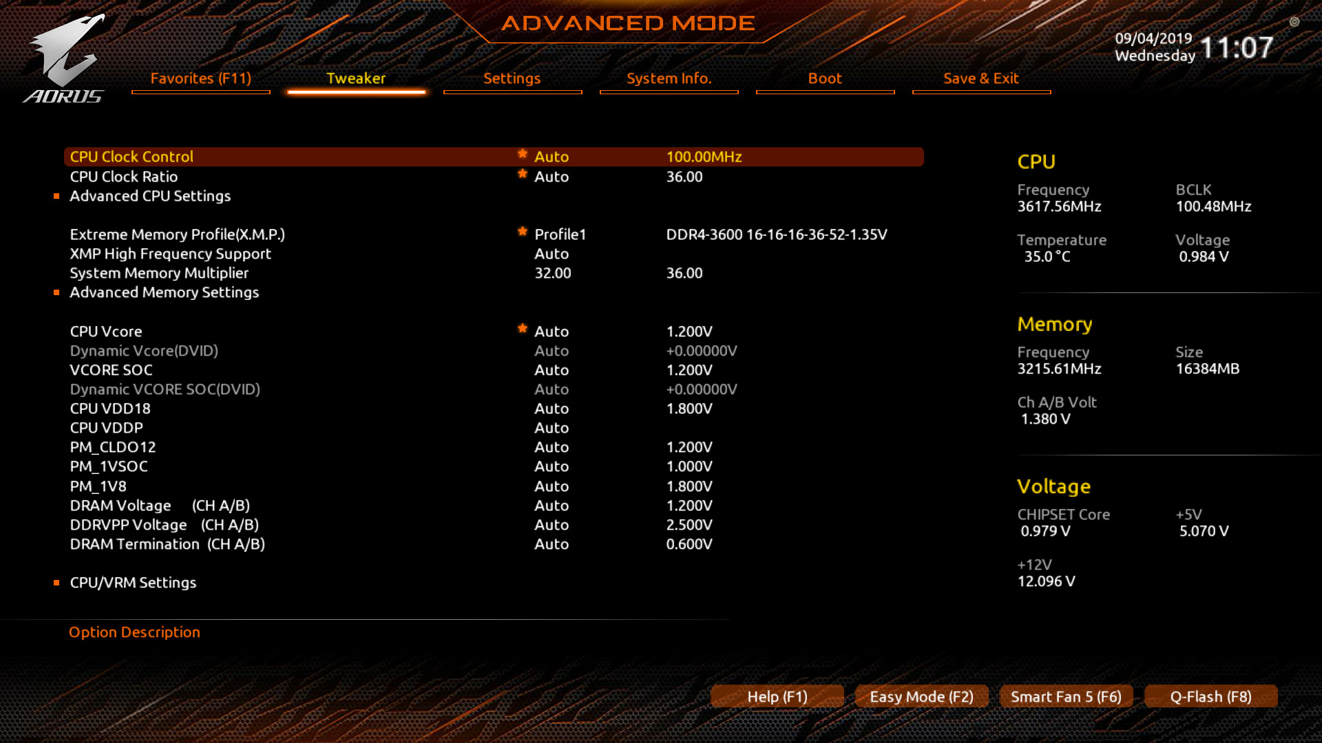
As with many vendors including its own pre-defined overclocking profiles, it's a little bizarre that a board of this pedigree has none for users to select from. Perhaps GIGABYTE has made an assumption that users looking to use the X570 Aorus Xtreme as the foundation for their new system might want to create everything themselves, but even a couple of basic profiles with general variables would have been nice to see; not everyone who spends a vast amount of cash is experienced in overclocking and profiles offer a gateway for novice users looking for extra performance from a simple click.
Overclocking Methodology
Our standard overclocking methodology is as follows. We select the automatic overclock options and test for stability with POV-Ray and OCCT to simulate high-end workloads. These stability tests aim to catch any immediate causes for memory or CPU errors.
For manual overclocks, based on the information gathered from the previous testing, starts off at a nominal voltage and CPU multiplier, and the multiplier is increased until the stability tests are failed. The CPU voltage is increased gradually until the stability tests are passed, and the process repeated until the motherboard reduces the multiplier automatically (due to safety protocol) or the CPU temperature reaches a stupidly high level (105ºC+). Our testbed is not in a case, which should push overclocks higher with fresher (cooler) air.
Overclocking Results
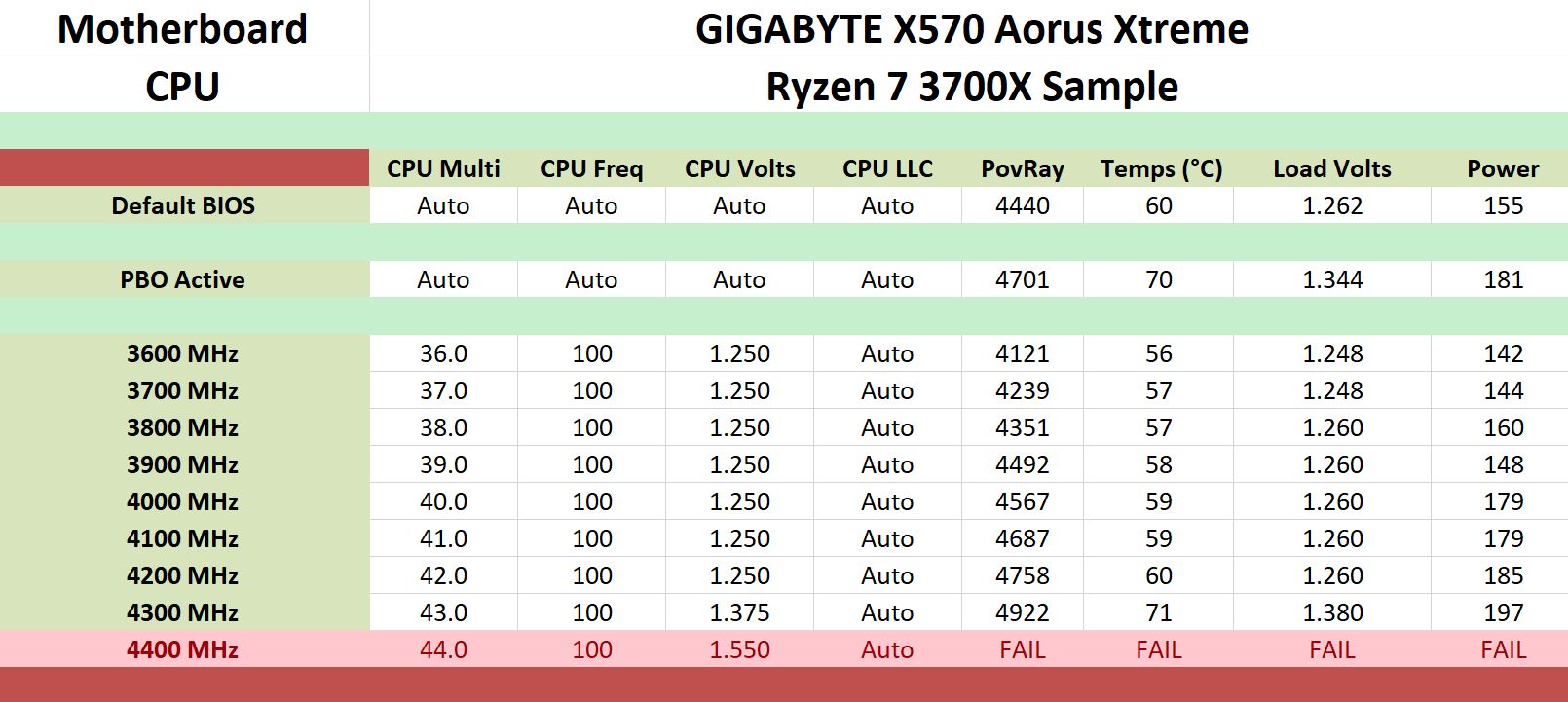
The lack of preset overclocking profiles can be forgiven due to the nature of how well the X570 Aorus Xtreme performs in our overclock testing. The overclocking performance of the GIGABYTE X570 Aorus Xtreme boasts very tight VDroop with the biggest variation from the value set for the CPU VCore in the firmware by a slight overcompensation of just 0.05 at our highest overclock of 4.3 GHz. Even at the lower frequencies ranging from 3.6 GHz all cores, to 4.2 GHz, we experienced a slight margin of variance by around 0.002 V to 0.01 V which is very impressive, to say the least.
GIGABYTE's biggest win here is that when Precision Boost Overdrive is in the firmware is set from default to enabled, the performance jump in our Pov-Ray testing yielded a massive improvement over stock settings; the score was increased from 4440 to 4701. While this equates to a performance jump of just under 6%, it's still something which other boards we've tested so far on earlier firmware have been able to achieve. Another interesting focal point is the power draw under load at our maximum settings of 4.3 GHz at 1.375 V on the CPU VCore. In comparison to the MSI MEG X570 Godlike which it competes in both spec and pricing, the X570 Aorus Xtreme managed to do this with 24 W of power draw. This shows the efficiency of the power delivery when extra voltage is put through Infineon's new 16-phase XDPE132G5C Digital PWM controller. Overall performance in Pov-Ray increased by a nice margin at each 100 MHz CPU ratio we tested, and we found no anomalies.


42 Comments
View All Comments
Smell This - Tuesday, September 24, 2019 - link
Maybe __ but I'm not sure I get your point.A conventional top down plugin has to bend 180-degrees to route under the tray as opposed to a 90-degree 'bend' ??
DanNeely - Tuesday, September 24, 2019 - link
A 90* plug doesn't get you anything unless you're routing the cable on the same side as the board (which isn't normal these days outside of SFF), or can make a tight 90* bend as the cable comes out of the routing hole. Unless you have a really flexible cable you're not going to be able to do that. Instead you end up having to make a 270* loop (up, then forward into where drive bays used to be, and then down and back to the board), so you still end up with a big loop.With a big loop a 180* can be done without putting any bending stress on the plug. A 270* either needs more cable to match the same bending radius or will have to be tighter and puts more stress on the board as a result. With the one system I had this sort of setup in there wasn't enough slack in the cable to do a loop with enough slack that it wasn't trying to bend/twist the board up. When I plugged the cable in before the board was screwed down it was flexing the board up when I tried screwing it down on the edge with the socket. With the board screwed down first, it was very difficult to get the plug to the socket partly because of the tray meaning I could only grip the cable from one side and partly because the cable didn't want to be bent tightly enough to go in. On the whole it was among the most frustrating build steps I ever did and the stiffness of the cable meant that it completely failed at the notional goal of keeping the wires out of the way that's normally behind 90* edge plugs.
My initial thought was that a rigid 90* adapter that extended out to the cable management hole would avoid the problem by removing the need to tightly bend the cable to fit. Thinking a bit more, that probably wouldn't be enough because making a tight bend behind the board would be just as difficult; you'd either need a 180* piece so the cable could stay flat on the backside of the board, or a short extension with all loose wires to make it work.
Ratman6161 - Tuesday, September 24, 2019 - link
How about this:https://www.newegg.com/cooler-master-cma-cemb00xxb...
Ratman6161 - Tuesday, September 24, 2019 - link
https://www.google.com/search?q=ATX+24+Pin+90%C2%B...MamiyaOtaru - Wednesday, October 9, 2019 - link
cool, connect that to the side plug and come at it from behind /seek2121 - Tuesday, September 24, 2019 - link
IMO we need a better solution for all the connectors that exist on motherboards. For example, those USB3 connectors. How many times have I bent a pin trying to plug one in when it accidentally gets pulled out? More than I'd care to admit. I mean hell, at least put a snap/latch on it similar to what most SATA cables have. Ideally, we've had 1 cable running from the case to the motherboard, and 1 cable running from the PSU to the motherboard. Both connectors would had the little snap or latch or whatever you call it, and both would be right angled so that they can easily be hidden from view for a nice clean look.DanNeely - Wednesday, September 25, 2019 - link
USB-C does use a smaller and more robust connector than USB 3.0 (you can see one on this board near the diagnostic code display) that appears to take its design inspiration from PCIe.A single cable from the PSU to the mobo would run into one size fits all problems and end up huge, ex the difference between the needs of an SFF system using a 4 pin CPU header and a high end work station/gaming board using 2x8pin CPU headers and a PCIe header (to give extra power for multiple GPUs).
What could be done easily enough would be to gut the 24 pin cable by making about half of its wires optional; even if not followed up by a new smaller plug/socket a few years later it would remove a lot of the headaches from the worst connector on the mobo. This could be done safely because the original 20 pin connector dates back to when the CPU ran on 3.3v, everything else ran on 5V, and hardly anything needed 12V; vs today when 5V is used almost exclusively for USB, 3.3V for odds and ends (eg 10 of the 25/75W a PCIe card can draw from the mobo is 3.3v not 12v), while everything else runs 12V to component specific voltage regulators.
The reason nothing's happened is more or less the same as why the mess of jumper style headers for the front panel has never been replaced by a standard block style connection. The PC industry as a whole no longer cares about desktops enough to expend the effort needed for a major new standardization round. Big OEMs can and do address the issues via proprietary components scoring spare part lockin as a bonus; while for everyone else (eg the people who make parts for customer built systems/boutique vendors) the upfront time spent and short term costs from needing to bundle legacy/modern adapters for a few years is too high to try and push something on their own. Residual trauma from the effort spent on the failed BTX standard some years back was probably an issue back when desktops were still important enough of a market segment to get serious engineering effort in standard modernization as well.
Dug - Monday, October 7, 2019 - link
I just have to chime in and agree with changing the entire layout. Look what oem's can do when they aren't tied to the ancient atx power supply and standard pin layout. Look at the power supply used on an imac pro. That's how it should be done. These giant cables and connectors are really unnecessary.4everalone - Tuesday, September 24, 2019 - link
I wish MB makers would start providing SFP+ ports instead of 10GBASE-T ports. That way we at-least have the option of running fiber/copper.TheinsanegamerN - Tuesday, September 24, 2019 - link
I like the look of the board and passive X570 cooling, but am dissapointed at the lack of expansion slots. No USB 3 header? Really? Just a gen 2 that cant be used on the vast majority of cases, and even if it can it will onyl feed a singular port? No PCIe x1 slots for, say, a USB 3 header card to make up for the lack of internal headers?Granted, this is a subjective problem, not many people use more then 1-2 slots, but for the price, I would want way mroe expansion for future upgrades. Think USB 3 headers, replacement NIC or sound cards in case of on board failure, NVMe cards for RAID arrays and better cooling, ece.